


Jiande Welfine Technology Co., LTD is a company with a high standard factory building of 14,000 square meters, in the beautiful scenic spot on the Xin 'an River by the bank of Qiandao Lake, focusing on powder metallurgy products for 21 years. We are a professional and experienced team dedicated to providing quality products such as bearings and automotive parts to customers around the world.Our main partners are from Europe and America, which proves that the quality of our products is recognized by the international market. We have our own independent laboratory, which can carry out strict quality testing on each batch of products to ensure that each product meets the requirements of customers.We believe that trust is built on quality and service, so we focus on product quality and customer service. Our products can be used with confidence and are a powerful assistant to your business success.We have a positive attitude, constantly innovate, improve process technology and quality standards, not only to satisfy customers, but also to make our employees proud and recognized. We will continue to build the highest quality products and services, become industry leaders, and create a better future.
company advantage
Professional team
We are a professional and experienced team dedicated to providing high-quality bearings, auto parts and other products to customers around the world.
QC
We have our own independent laboratory that can conduct strict quality testing on each batch of products to ensure that each product meets customer requirements.
Rich experience
We focus on powder metallurgy, with 17 years of experience, and have won a good reputation, quality and integrity in this field.
Customer service
We earn your respect by delivering on time and on budget. Our reputation is built on excellent customer service. Discover the difference it makes.
Related Product

If you are interested in our powder metal gear, please don't hesitate to contact us, we will provide samples and quotations as soon as possible!

If you are interested in our Pinion Gear quora, please feel free to contact us, we will provide samples and quotations as soon as possible!

Powder Metallurgy Sintered Iron Gear
Sintered Fe-Cu Alloy and sintered Fe-Cu-C are the most application in the production of sintered structural parts and different Powder Metallurgy Sintered Iron Gears.

Gear is generally used in the need for compact transmission structure, variable speed, variable speed ratio, transmission power (torque, speed), high transmission accuracy "place". Gears are widely used in automobiles, tractors, engineering machinery, ships, machine tools, mining machinery and other fields. Gears are used in almost all mechanical devices.

Our Metric Pinion Gears exemplify precision and durability in mechanical engineering. Crafted to exacting standards, they offer efficient power transmission across diverse industries. With optimal tooth profiles and strict adherence to metric specifications, these gears ensure steadfast performance and precise motion control. From industrial machinery to automotive systems and robotics, they embody excellence, providing robustness, efficiency, and compatibility for various applications.

Our Metric Gears exemplify precision and durability in mechanical engineering. Crafted to exacting standards, they offer efficient power transmission across diverse industries. With optimal tooth profiles and strict adherence to metric specifications, these gears ensure steadfast performance and precise motion control. From industrial machinery to automotive systems and robotics, they embody excellence, providing robustness, efficiency, and compatibility for various applications.

Structure Parts Sintered Gears
Gears have many typical applications. Such as Power Tools, Agriculyural Machinery, Home Appliancess.

Engineered with precision-cut teeth arranged in a straight line along their cylindrical surface, stainless steel Pinion Gears efficiently transfer rotational motion between parallel shafts. Their simple yet effective design ensures smooth and precise power transmission, providing consistent speed and torque output.

Our small Pinion Gears are meticulously manufactured with precision-cut teeth and optimal gear profiles, ensuring seamless power transmission and minimal noise during operation.
What is Pinion Gear
A Pinion Gear is a cylindrical toothed gear with teeth that are parallel to the shaft and is used to transfer mechanical motion and control speed, power, and torque between shafts. They are the most popular types of cylindrical gears and have a simple design of straight parallel teeth positioned equally around the circumference of the cylinder barrel. There are several different designs of Pinion Gears that change according to the shape and thickness of the gear hub, which changes without changing the face of the gear.
Benefits of Pinion Gear
Simple Design
The simple compact design of Pinion Gears makes them easy to create, design, and configure. They can fit easily into restricted and tight spaces with few limitations.
Precision and Accuracy
This aspect of Pinion Gears is one of the major reasons for their wide usage. Pinion Gears increase and decrease speed with exceptional precision and accuracy at a constant velocity.
Gear Reliability
It is very unusual and unlikely for a Pinion Gear to fail during use. Their durability and strength make it next to impossible for them to slip, break, or malfunction.
Production Cost
This is another factor that has made Pinion Gears so indispensable. Their simplicity makes it easier to manufacture them, which greatly decreases their production cost. Large volumes of Pinion Gears can rapidly be produced with little waste.
Pinion Gear Efficiency
Efficiency works in conjunction with reliability. During the useful life of a Pinion Gear system, the gears are able to transfer large amounts of power across several gear trains without any or minimal loss of power.
Straight Teeth
The straight teeth of Pinion Gears eliminates the likelihood of axial thrust since power is transmitted in a straight line at the pitch angle of a Pinion Gear's teeth.
Pinion Gear Uses
Changing Speed
In applications that require the increase or decrease of speed, Pinion Gears are an ideal solution. They transfer motion and power from one shaft to another, which alters the operating speed of machinery, multiplies torque, and allows for fine tuned control of positioning systems. It is for this reason that they are found in clocks to adjust the speed of second, minute, and hour hands.
Washing Machines
Since Pinion Gears control the speed of applications, they are used in washing machines to control the rotating motion of a washing machine. Depending on what cycle the machine is performing, Pinion Gears assist in increasing or decreasing torque.
Road Roller
In a road roller, a set of Pinion Gears changes the fast rotational speed of the engine into a slow rotational speed for the wheels. This change makes it possible for a road roller to be able to move its heavy roller.
Sports Car
In a sports car, a smaller rotational force is needed for the wheels because a sports car is very light. Pinion Gears used to move a sports car also change the engine's speed into a slower rotational speed for the wheels. The wheels are able to turn faster with a smaller turning force.
Conveyor Systems
Conveyor systems have to move at a controlled speed, producing high torque. Pinion Gears are used as a reliable means for altering the torque of the system. In some types, a self-locking worm gear is used to power and move the Pinion Gear, where the worm gear is the drive gear.
Types of Pinion Gear
The split hub has a split along its axial plane, which allows it to be attached to any shaft by having the split hub tightened with a clamp to snuggly and securely attach it to the shaft. It is one of the easiest Pinion Gears to assemble and disassemble. Split hub Pinion Gears can adjust and configure their position on the shaft with little effort. The drawback to split hub Pinion Gears is their size since they tend to take up more space.
The teeth for an internal Pinion Gear are cut on the inner surface of the gear. The external surface is smooth in the shape of a perfect oval or circle. The inner gear teeth mesh with a pinion or smaller gear. The gears rotate in the same direction.
With a spline Pinion Gear, ridges or teeth are cut into the drive shaft that matches grooves cut in the bore of the Pinion Gear. There are different varieties of spline configurations with some straight like a keyway or involute like gear teeth. The spacing between the splines varies according to the design of the gear. Involute spline Pinion Gears can have any number of teeth up to 32.
A pin hub Pinion Gear has a set screw used to secure a pin on the gear to the shaft. They can be connected to a shaft using a dowel, spring, roll, or taper pins. The hole in the gear is drilled to the exact size of the pin for a tight connection. The set screw used to pin the gear to the shaft is removed to avoid loosening and falling into the mechanism. The difference in the various types of pin hub Pinion Gears is the size of the hole where the gear connects to the shaft.
With a keyway Pinion Gear, a slot is cut in the gear's bore that fits the slot milled into the shaft. The keyway allows the shaft and gear to fit snugly together with the proper alignment of the slots. The purpose of the design is to eliminate slippage between the shaft and Pinion Gear.
Components of Pinion Gear
Pitch Circle
The pitch circle is the distance from the face of one tooth to the next tooth. It divides a gear's teeth into the top of a tooth, the addendum, and the bottom of the tooth, the dedendum. If a gear system is designed correctly, pitch circles between gears will be tangent to one another.
Diametral Pitch
The diametral pitch is a function of a gear's pitch circle and is equal to the number of teeth per inch. It is used to determine what size and type of gear are needed to interlock with another gear.
Pitch Diameter
Pitch diameter is the outer diameter of a gear as if a circle was drawn around the midpoint length of each tooth of a gear. It is used to determine the distance between mating gears, as seen in the diagram below.
Center Distance
The center distance is the distance between the centers of two meshed gears and is the sum of the pitch diameters divided by two.
Root Diameter
The root diameter is the diameter of a circle that could be drawn around a gear and coincides with the bottoms of all teeth. It is a diameter that could be drawn across that circle.
Pressure Angle
The pressure angle is the angle between the pitch line and the pressure line where the pressure line is tangent to the pitch point and is normal to the tooth surface. A diagram of it can be seen in the image below.
Pinion Gear Materials
There are several types of plastics used to produce plastic Pinion Gears, including polyacetal (POM), nylon, polyethylene (UPE), and polyetheretherketone (PEEK), a ketone polymer. Plastic Pinion Gears are lightweight, rust resistant, inexpensive to produce, and can operate without producing friction. They are widely used in food production, electronics, toys, and medical instruments.
POM is a very strong plastic commonly used to produce Pinion Gears. It can be easily molded, shaped, and formed. Once it hardens, POM becomes extremely stiff, strong, and abrasion resistant. The malleability and resilience of POM make it an ideal material for Pinion Gear manufacturing.
Cast iron, like POM, can be molded into any shape and is resistant to rust. The composition of cast iron involves the use of different ingredients each of which gives cast iron a different degree of strength and durability. Cast iron is commonly used to produce machine parts because of its low cost, rust resistance, and ability to be easily molded and shaped. It can be unbelievably strong or very weak, depending on the types of added mixtures.
Stainless steel comes in several levels, grades, and characteristics, with all types having at least 11% chromium. Other alloys include nickel, manganese, silicon, phosphorus, sulfur, and nitrogen. Ferritic stainless steels are magnetic, while austenitic stainless steels are nonmagnetic, martensitic, and precipitation hardened. Austenitic stainless steels are in the 300 series of stainless steels, while ferritic stainless steels are in the 400 series.
How to Choose Pinion Gear
Torque and Speed
The calculation of the torque and speed of a system is essential when selecting the proper Pinion Gear. This refers to the input speed and input torque and the output speed and output torque.
Identifying Through Pitch
Pitch is an identifier for Pinion Gears and includes the diametrical pitch, circular pitch, and module. In the United States, the designation of pitch is the diametrical pitch (DP), which is infinite. To make choices easier, a specific set of DPs has been developed.
Teeth Geometry
Gear teeth geometry is determined by the pitch, depth of the teeth, and pressure angle. A complex set of formulas are required to make the teeth geometry calculation.
Idler Gear
Idler gears are used to change the directional rotation of the output gear. When designing Pinion Gears, it is necessary to know whether an idler gear is required.
Gear Trains
Gear trains are used to pass power between shafts and are a series of Pinion Gears with similar gear shapes and teeth.
Stress Calculations
Several forms of stress calculations must be made regarding a Pinion Gear system. The purpose of the calculations is to ensure the safety and strength of the system.
Type of Material
The type of material determines the longevity of a Pinion Gear and its strength, reliability, and endurance. This aspect of the selection process is normally the first consideration and is carefully planned by designers and engineers.
Process Of Pinion Gear
Regardless of the cutting process, it begins with a gear blank. The quality of a Pinion Gear depends on the type of material from which the gear blank is made. High quality Pinion Gears can only be made from high quality materials, which is a pie shaped billet.
The milling process can produce all types of gears beyond Pinion Gears. It involves using a milling machine that has a form cutter that passes through the gear blank to cut the tooth gap. In form milling, the workpiece is mounted such that the cutter can move perpendicular along the axial length of the tooth at the correct depth. At the end of each cut, the cutter is withdrawn, and the gear blank rotates for the next cut. The cutter has the shape of the space between the teeth.
In the hobbing process, the gear blank and the hob rotate simultaneously in a continuous motion such that they mesh as the teeth are being cut. The tool or hob is fed inward until it reaches the proper depth and has equally spaced cutting edges. Hobbing is a fast and accurate process.
The gear shaping process can be used to create internal Pinion Gears and has a cutting tool that is a gear with cutting edges that moves axially against the inner diameter of the workpiece. The cutting gear rotates at the same velocity ratio as the gear being made. The motion of the cutting tool is repeated several times until the proper depth is reached for the gear teeth. It is a slow process that involves rotating the tool and workpiece as the tool continues its oscillating motion.
In the stamping process, a sheet of metal is placed between the top and bottom dies where the upper die is pressed down on the lower die cutting out the gear from the sheet. It is a low cost efficient method for producing lightweight Pinion Gears for medium duty with no loads. Stamping is restricted by the thickness of the metal, which ranges in thickness from 0.25 mm or 0.010 inches to 3 mm or 0.125 inches.
The roll forming of Pinion Gears requires several rotations of the forming rolls where the rolls are fed slowly during several revolutions. Top lands of roll formed teeth may not be smooth or perfect in shape. Since the top land does not affect the action of the teeth, this deformity does not cause any difficulty.
How to Maintain Pinion Gear
Regular Inspections
Perform routine visual inspections of the gear system to detect any signs of wear, damage, or misalignment. Check for abnormal noise, vibration, or leakage. Inspect gears, bearings, seals, and lubrication conditions.
Lubricant Monitoring
Monitor the condition of the lubricant regularly. Check for contamination, degradation, or insufficient levels. Perform oil analysis to assess viscosity, particle contamination, and lubricant condition. Change the lubricant as recommended by the manufacturer.
Gear Meshing Inspection
Periodically inspect the gear meshing to ensure proper tooth engagement and alignment. Check for abnormal wear patterns, scoring, pitting, or tooth damage. Address any issues promptly to prevent further damage.
Bearing Maintenance
Pay attention to bearing performance and conditions. Monitor for excessive noise, vibration, or temperature. Regularly lubricate bearings as per manufacturer recommendations. Replace bearings when signs of wear or damage are observed.
Sealing and Protection
Ensure proper sealing and protection of the gear system against contaminants, moisture, and environmental factors. Replace damaged or worn seals and gaskets. Keep the gear housing clean and free from debris.
Temperature Monitoring
Monitor the operating temperature of the gear system. Abnormal temperature increases can indicate issues such as overloading, insufficient lubrication, or misalignment. Address temperature abnormalities promptly to avoid gear system failure.
Maintenance Records
Maintain comprehensive records of maintenance activities, inspections, and repairs performed on the gear system. This information helps track the gear system's history, identify recurring issues, and plan maintenance tasks effectively.
Professional Assistance
If you encounter complex issues or challenges during installation or maintenance, consider seeking assistance from qualified gear engineers or technicians. Their expertise can help diagnose and address problems effectively.
Our Factory
Jiande Welfine Technology Co., LTD is a company with a high standard factory building of 14,000 square meters, in the beautiful scenic spot on the Xin 'an River by the bank of Qiandao Lake, focusing on powder metallurgy products for 21 years. We are a professional and experienced team dedicated to providing quality products such as bearings and automotive parts to customers around the world.Our main partners are from Europe and America, which proves that the quality of our products is recognized by the international market. We have our own independent laboratory, which can carry out strict quality testing on each batch of products to ensure that each product meets the requirements of customers.We believe that trust is built on quality and service, so we focus on product quality and customer service. Our products can be used with confidence and are a powerful assistant to your business success.We have a positive attitude, constantly innovate, improve process technology and quality standards, not only to satisfy customers, but also to make our employees proud and recognized. We will continue to build the highest quality products and services, become industry leaders, and create a better future.


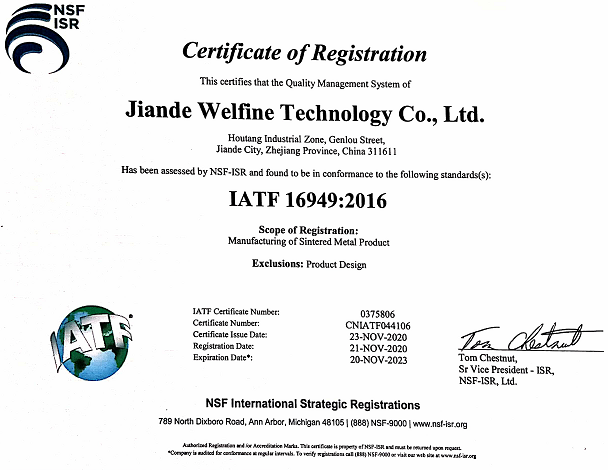
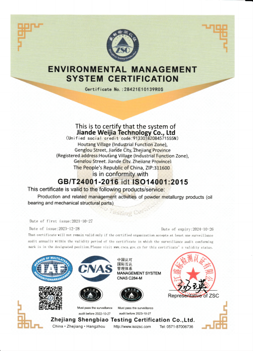
Certificate



FAQ
Q: What is spur vs bevel gear?
Q: What are the advantages and disadvantages of Pinion Gears?
Q: What is a spur vs helical gear?
Q: What is the difference between a traditional gear and Pinion Gears?
Q: Why are Pinion Gears better?
Q: Are spur or helical gears stronger?
Q: Do bikes use Pinion Gears?
Q: What is the alternative to a Pinion Gear?
This causes more than one tooth to be in contact during operation and helical gears can carry more load than Pinion Gears. Due to the load sharing between teeth, this arrangement also allows helical gears to operate smoother and quieter than Pinion Gears.
Q: Which gear will turn the fastest explain why?
Q: What is the most efficient type of gear?
Q: What is a Pinion Gear used for?
Q: Why are Pinion Gears loud?
Q: Do cars use Pinion Gears?
Q: Is a smaller Pinion Gear faster?
Q: What does pitch mean on a Pinion Gear?
Q: How long do Pinion Gears last?
Q: What is the maximum speed of helical gears?
Q: Are helical gears left or right handed?
Q: Can helical gears be reversed?
Q: Why are helical gears quiet?
Hot Tags: pinion gear, China, suppliers, manufacturers, factory, wholesale, customized